9/22/2013

Main Motor and Rotor Assembly for MUZL 610TW Type Pellet Mill

Main motor

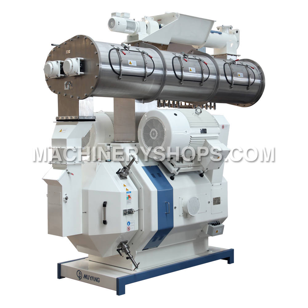
This type of pelleting machine includes two main motors, which are symmetrically installed at both sides of the pellet mill.

The two motors shall rotate in the same direction and finally the ring die shall rotate in clockwise.

The two motors shall startup in star form at the same time, while under normal operation speed the one is transmitted to a triangle connection firstly, and the other also to a triangle operation about five seconds later.

Two motors must run at a same direction and commissioned separately before commissioning and starting of this machine.
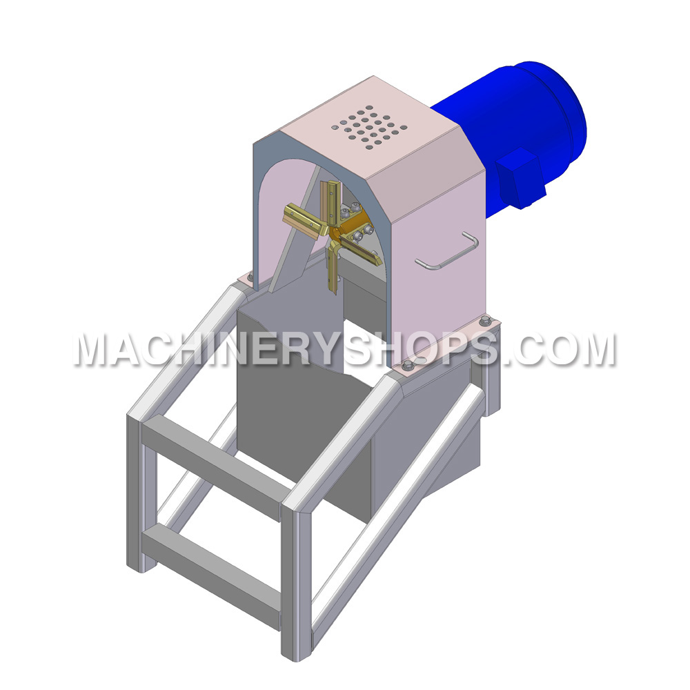
Rotor assembly

Main components of rotor assembly are shown in Fig 2.3.

The oil-way of rotor assembly shall be kept unobstructed, after filling the oil from oil nozzle of distributer at rear end, the lubricating oil leading to press roller bearings shall overflow from the seal plate at the end of the press roller after being filled up, and lubricating oil leading to rotor bearings shall overflow from the clearance between the rotor and main shaft disc after being filled up.(It is guaranteed by the oil seal installation direction of the rotor)

Generally, in good lubrication, the service life of the bearings and oil seals of the rotor are longer and they are uneasy to be damaged. It is suggested to ask pellet mill experts of Muyang Group for guide when replacing bearings and oil seals.

Pay attention to abrasion of the cone face of driving flange of the ring die, see Section 7.5 for assembling and disassembling as well as maintenance.


Shear pin assembly

The main parts of the shear pin assembly are shown as Fig.2.5.

When there is large iron block or other impurities entering between the ring die and press roller, in which case, the toque delivered by main shaft will exceed the shear force of the shear pin (part 3), and the shear pin will be sheared off and drove the main shaft rotating with the rotor, the limit switch (part 5) will be cut off to stop the main motor, and take the effect of protecting ring die and press roller.

Restore the Shear pin disc (part 2) to replace a new shear pin after it is sheared off.

9/18/2013

MUZL610 Series Pellet Mill

MUZL610-type pellet mill is an advanced pellet mill, which is of Jiangsu Muyang Group manufactured. The entire manufacturing process is in full accordance with international technical standards.

Application and adaptability
(1) This pellet mill is specially used for animal feed processing, generally for processing powdery, foldable and easily pelletized materials.
(2) For ensuring the operation safety of the machine, the altitude of the service region of this machine should be less than 1000m, temperature range 5℃~40℃, and air relative humidity range 30%~ 85%.
(3) Do not used in food processing.
(4) When the region does not accord with the above conditions, in order to be given special instructions.


Main features and functions of the equipment
(1) MUZL610-type pelleting machine is an advanced pellet mill, which is of Jiangsu Muyang Group manufactured. The entire manufacturing process is in full accordance with international technical standards.
(2) Double-motor and V-belt driving system is adopted for this machine type, which is characterized by ideal drive ratio, great driving moment, smooth rotation, high output, low noise, and easy operation and maintenance.
(3) This type of machine can be fitted with many kinds of ring dies with φ1.5~ φ12 die holes and different thickness, so customers can select them for use as required to achieve the optimum technical and economic efficiency.
(4) Advanced frequency control motor is adopted for this machine type to feed material, equipped with overload protection devices, outside discharging mechanisms and Magnetic separating device.
(5) Various conditioners are available, such as single-conditioner, double-conditioner, triple-conditioner, different diameter cylinder conditioner and feed etc.

9/17/2013

Installation of Bridge-breaking Feeding Bin and Feeder

One of basic reference data for the control system of the extruder is the material flow rate, and the addition level of water, steam and other liquids in the system shall refer to the material flow rate, therefore the stability of material flow will directly affect that of the whole extruder producing. To ensure stable materials flow, weighing feeding is used in this system, namely, put the whole feeding bin and feeder onto the weighing sensor, so as to form a closed-loop control among weighing sensor, frequency-converted feeder and computer, and then realize feeding.

A basic requirement to the weighing feeding of the feed extruder is a flexible connection between upper and lower interface, namely, the flexible connection between bridge-breaking feeding bin and pneumatic gate at upper part of the bin, as well as the flexible connection between feeder outlet and conditioner inlet, canvas is usually used as the material for flexible connection for this two parts.


Installation of weighing sensor is another important factor affecting the feeding. There are generally two methods for sensor installation: hanging installation and supporting installation, which will be used as required in the site. Necessary measures shall be taken to ensure stability of bin body while hanging installation is used. During production of extruding machine, falling down of materials, when feeding to the feeding bin, will make the whole bin body waggled, the waggling extent and time will closely related to the length of sensor's tie bar. Although the control procedure uses the data prior to feeding for the data in the period of material entering the bin, waggling of the body will be also caused after material enters the bin, the weighing accuracy of sensor will be directly affected, and thus the control procedure will also be influenced, therefore it is required to equip with a limit device at the lower part of bin, and this device shall not affect weighting.


The another method is supporting installation, which will not cause waggling, but the whole bin body on the extruding machinery tends to translocation, therefore sensor should be fixed on a bracket during installation, and it is required to mount limit blocks at both sides of each ear of the feeding bin, so as to prevent the whole bin body from translocation.

It is necessary to pay attention to the position of access door during installation of bridge-breaking feeding bin, and the maintenance platform should be mounted at the lower part of access door while ensuring that the access door can be opened.

9/16/2013

Important Explanation on SWFP Series Fine-grinding Hammer Mill

Congratulations on your purchase of Muyang Brand Hammer mill. This design of Chaoyue Fine-Grinding Hammer Mill can both fulfill your requirements to grind different raw materials and also improve the material grinding efficiency. Prior to use, please read through this Operation Manual and well know the safety points, different performances, requirements to installation and operation etc. For this Hammer mill, so that you can expertly operate and use this machine, and create more benefits for you.

This Operation Manual shall be provided to your working personnel in charge of operating and managing the equipment manufactured by Jiangsu Muyang Group which is a successful grinding machine manufacturer. Therefore, it is very important to deliver these documents to them.


A check on appearance should be made immediately when the equipment is transported to the destination. If it is sure there is any damage caused during transport, a necessary claim procedure must be taken according to the supply contract. The repair expense shall be borne by relevant risk undertaker.

The grinding machine, which cannot be installed in predetermined place immediately, must be stored in a weatherproof place with facilities against external infringement in original packages. Any loss arising from storage shall be only conducted as per the principle specified in the Supply Contract.

The equipment and parts manufactured by Jiangsu Muyang Group shall be installed only by the trained technical personnel based on installation specifications provided together with the equipment.

If several structures on the grinding machinery are introduced in the documents provided, only the structures specified in Supply Contract shall be effective. We reserve the right of improvement before delivery.

Startup and commissioning shall only be done by trained personnel. The operators shall know the instructions and operation regulations in provided documents before startup. Lubricating oil shall be filled before startup, such as oil for variable speed devices.

The accident prevention rules in related documents must be well known and strictly obeyed. Jiangsu Muyang Group devotes to manufacturing machinery equipment according to the latest National Safety Standards (CE Certification Standards). Customers shall tell us the local safety rules before manufacturing. Additional expenses there from shall be borne by customers.

The leaders of an enterprise owning the equipment from Jiangsu Muyang Group shall have the duty to allow the operators to know the operating instructions, and shall point out where the especial dangers are during operating these grinding machines.

9/12/2013

Muyang Chaole Series SWFL 110B/C Ultra-fine Pulverizer

SWFL B/C series vertical ultra-fine pulverizer is a new type of equipment for large-, medium- and small-sized feed mills to process various coarse ground materials after preliminary cleaning, magnetic separation and mixing, such as corn, sorghum, rice, wheat, soybean meal, fish and shrimp, so as to obtain the materials in superfine particle size as required. It is especially suitable for fine grinding or ultra-fine grinding of feeds for prawn, turtle, eel and young animals.

SWFL B/C series ultra-fine grinding machine mainly consists of a stander, a grinding system, a grading system, a feeding system, a hydraulic opening mechanism as well as a main motor driving part for grinding and a motor driving part for grading (see Fig.1). The grinding system is composed of a main shaft, a grinding disc, a toothed ring and a grinding chamber; the grading system is composed of a grading impeller shaft, a grading impeller, a convex cover and a discharge chamber. The main motor runs in vertical driving way; the frequency conversion motors with frequency converters are used for both grading and feeding, so as to realize steeples speed regulation and remote control.


Preparation and inspection prior to first test run

1. Open the grading system, and check for any metal or sundries in the grinding chamber;
2. Check for any metal or sundries in the feeding bin or feeding screw;
3. All fasteners must be carefully checked for any looseness;
4. Check whether the driving belts are properly tensioned and the guard hood is well mounted;
5. Check each driving part on the grinding machinery for collision, analyzes the reason if any, and then put it right as soon as possible;
6. Turn each driving part and see whether there is any abnormality, and then inch each driving part and check whether they rotate in a correct direction;
a. The rotating direction of the grinding disc: clockwise in an overhead view.
b. The feeding screw: rightward.
c. Rotating direction of the grading impeller, normally it is clockwise in an overhead view. It can also be changed into counterclockwise according to actual situation.
7. Keep idle run of the hammer mill for 20-30 min. and observe its current, temperature and vibration: The temperature rise of the main shaft bearings should not exceed 35, and the maximum ℃temperature should not exceed 70 ℃(the ambient temperature should not exceed 40 ℃). The vibration amplitude of the machine should not be too large. And the machine cannot be loaded until it runs idly in a normal way.
8. During working, properly open the upper air gate of the gravity impurity removing chamber of the machine. And adjust the position of balance weight block on the gravity cover that is at the bottom of the machine so that it can open automatically when there are many impurities.

9/11/2013

Major Component on MY56×2A Twin-Screw Extruder

Cutting device

As an important component, the cutting device has a great effect on the sustained and steady running of the extruder as well as the pellet form of expanding feed. The cutting device is mainly composed of a slide rail, housing, a screw moving device and a cutter driving unit, see Fig.3.7.


When working, slide the housing as well as the cutting driving device to the working place and fix. The cutter driving unit can be adjusted forward by turning the screw on the screw moving device when there is any wore on the cutter during working, which can ensure the clearance between the cutter blade and the die plate on the feed extruder keep appropriate. After working, the housing and cutter driving unit should be slide to the other side of the slide rail and then fixed.


Cutter driving unit

1. The driving component for cutting consists of cutting knives and a driving device with variable speed. A variable frequency speed control motor is applied for variable-speed driving; the cutting knife bar drives the cutting knives to rotate. The length of product to be cut is cont rolled by adjusting the rotating speed of the cutting knives.
2. There is a long hole in the knife support, through adjustment its position on the knife tray, the edge surface of knife can be in a surface.

Discharging device

In comparison with discharging device (I), a "8" shaped hole spacing plate is added in discharging device (II), and the others are the same except length of the screw.
The material extruded and ripened in extruder chamber must be formed through a discharging device and the discharging device is mainly used for limiting the flow of material to form the required pressure for expanded material at the end of expanding chamber. Structure of discharging device and selection of die can directly influence the quality of material.
The discharging assembly of this extruding machine mainly consists of "8" shaped bus bar and five die plates are available for this extruder.


Bypass

The bypass is located between outlet of different diameter cylinder conditioner and the inlet of extruding assembly. The flow direction of material from the conditioner can be selected through bypass: flow into inlet of extruding assembly for extrusion or flow out through chute of the bypass in convenience for checking conditioning efficiency of material.

Safety Specification for Operation of Pellet Mill

In order to ensure the safety of electric circuits and avoid explosion resulted from spark discharge, the paint coat at the electric connections must be removed, to make them earthed reliably.


General safety points
1. This machine shall be operated by trained and designated workers.
2. The main power supply must be cut off when making repairs and maintenance work, and it is forbidden to open the operation gate until the equipment is stopped fully.
3. When the machine is running, it is strictly forbidden to put fingers near the running parts, such work as inspection, maintenance and cleaning etc cannot be done until the rotor of Pellet Mill has completely stopped.
4. Wear protective gloves (max. temperature of ring die, press roller and other parts can be high up to 100℃), safety shoes with steel plate and safety helmets when making repairs and maintenance work.
5. It is not allowed to take off the guard for machine when running.
6. In case maintenance and inspection work should be done with a welder or other tools that can generate sparks, strict safety precautions must be taken against dust explosion and combustion.
7. The electric control device provided by Jiangsu Muyang Group is an integral part of the Accident Prevention Safety Plan, which shall be checked and approved in writing by experts of Muyang Group before startup. If any control system used for the equipment produced by Jiangsu Muyang Group is provided by a third party, it shall be manufactured according to the specifications of Muyang Group, and shall be checked carefully and approved in writing by an expert from Muyang Group before startup. If the control system for Muyang machinery equipment is not manufactured as per the quality standard, the Muyang Group will refuse to take any responsibility and the Group will reserve the right to investigate and affix the responsibility of the operator.
8. The interlocking limit switch is installed for opening the operation gate of Pellet Mill, the strict wiring must be ensured for cutting off the switch when opening the gate and the equipment cannot be started up after opening the operation gate. This safety device is concerned in life safety, so it may not be re moved or discarded, and shall be repaired or replaced immediately when any malfunction occurs.
9. Electric installation and the treatment of conducting parts can only be done by specialized persons in accordance with the national electric safety standards.
10. Keep the safety device in pelleting machine in good condition and regularly check its function, for instance once every month.
11. When the machine is under shutdown, attention must be taken to prevent it from being started by any starting mode.
12. Before the electric circuit is cut off, it is strictly prohibited to open the terminal box for avoiding electric shock.